MEP Cable Routing System
Purpose
Automatically places light fixtures and switches in each room, then computes optimal cable paths using A* pathfinding on a waypoint graph. Produces realistic right-angle cable routes that follow electrical installation conventions.
Files
| File | Role |
|---|---|
tools/_mep_utils.py |
Geometry extraction: spaces, doors, fixture placement |
tools/_spatial_graph.py |
Waypoint graph construction + A* pathfinding |
tools/mep_routing.py |
Tool wrapper: orchestrates extraction → graph → routing |
Calculation Steps
Step 1: Extract Building Geometry (_mep_utils.py)
extract_spaces(model)
- Iterates all
IfcSpaceelements - For each: gets placement matrix, computes world-space bounding box via
_compute_extrusion_bbox() - Returns:
[{id, name, long_name, global_id, bbox_min, bbox_max}]
extract_doors(model)
- Iterates all
IfcDoorelements - Gets placement origin from
ObjectPlacement - Finds parent wall via IFC relationship chain:
door.FillsVoids → opening.VoidsElements → wall - Returns:
[{id, name, position, width, height, parent_wall_id}]
Step 2: Fixture Placement (_mep_utils.py)
compute_light_position(space)
light = [
    (bbox_min[0] + bbox_max[0]) / 2,    # center X
    (bbox_min[1] + bbox_max[1]) / 2,    # center Y
    bbox_max[2] - 0.05                   # 5cm below ceiling
]
compute_switch_position(space, door)
- Determine which face of the space bbox the door is on (nearest face detection)
- Place switch at:
- Along wall:
door_edge + half_width + 0.15m(15cm from door frame) - Height:
Z = 1.05m(standard switch height) - Depth: on the space's bbox face (wall surface)
find_door_for_space(space, doors)
- Geometric proximity: door position within space bbox + 0.35m tolerance
- Door must be near a face (not deep inside the space)
Step 3: Build Waypoint Graph (_spatial_graph.py)
build_room_graph(space_bbox_min, space_bbox_max, light_pos, switch_pos)
Creates a lightweight graph (~10-15 nodes per room) with strategic waypoints:
Nodes:
- "light" — light fixture position
- "switch" — switch position
- "light_ceil" — ceiling point above light
- "switch_ceil" — ceiling point above switch
- "ceil_sw/se/nw/ne" — 4 ceiling corners (offset 10cm from walls)
- "ceil_L1" — L-shaped intermediate at (light_x, switch_y, ceiling_z)
- "ceil_L2" — L-shaped intermediate at (switch_x, light_y, ceiling_z)
- "wall_ceil_switch" — ceiling edge point on the switch's wall
Edges (axis-aligned only): - Vertical: light↔light_ceil, switch↔switch_ceil (cost 1.0×) - Ceiling: only between nodes sharing the same X or Y (no diagonals) - Wall: switch_ceil↔wall_ceil_switch (cost 1.1×) - Edge weight = Euclidean distance × cost multiplier
Why axis-aligned only:
Real electrical cables run in straight lines with 90-degree bends.
Diagonal connections are not created, forcing L-shaped routes through
the intermediate nodes ceil_L1 and ceil_L2.
Step 4: Find Route (_spatial_graph.py)
find_route(graph, source="light", target="switch")
- Uses
networkx.astar_path()with Euclidean distance heuristic - Returns ordered list of node IDs
route_to_points(route, graph) + simplify_route(points)
- Converts node IDs to 3D coordinates
- Removes collinear intermediate points
Step 5: Output (mep_routing.py)
Returns table data + route geometry:
{
  "title": "MEP Cable Routing",
  "summary": "2/2 rooms routed, total cable length 9.8m",
  "columns": ["Space", "Light Position", "Switch Position", "Cable Length", "Status"],
  "rows": [["Raum 1", "(3.30, 7.70, 2.39)", "(4.39, 5.30, 1.05)", "4.89m", "4 segments"]],
  "routes": [{
    "space_name": "Raum 1",
    "points": [[3.30, 7.70, 2.39], [3.30, 7.70, 2.42], [4.39, 7.70, 2.42], [4.39, 5.30, 2.42], [4.39, 5.30, 1.05]],
    "type": "electrical",
    "terminals": {
      "source": {"type": "light", "position": [3.30, 7.70, 2.39]},
      "target": {"type": "switch", "position": [4.39, 5.30, 1.05]}
    }
  }]
}
Typical Route Path
Light (center ceiling)
  ↓  short vertical stub to ceiling surface
Ceiling
  →  horizontal run along ceiling (axis-aligned)
  →  turn 90° (L-shaped bend via intermediate node)
Wall above switch
  ↓  vertical run down wall to switch height
Switch (1.05m height, next to door)
3-5 segments, all right-angle bends, matching real electrical installation practice.
Viewer Visualization
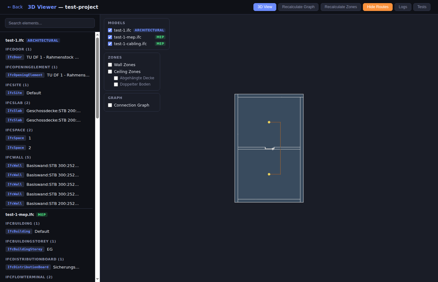
- Toggle: "Show Routes" / "Hide Routes" button
- Orange cylinder tubes (radius 0.015m): cable path segments
- Orange spheres (radius 0.025m): bend joints at waypoints
- Yellow sphere (radius 0.12m, emissive): light fixture
- White box (0.08×0.12×0.03m): switch
- Coordinates transformed via
ifcToThree()before rendering
Future: GNN Layer (Phase 2)
The waypoint graph + A routes serve as training data for a future Graph Neural Network: - GraphSAGE/GAT model learns optimal edge costs from A routes - Node features: position, distance to walls/ceiling/floor, terminal type - Edge features: length, direction, is_vertical, is_ceiling_run - Inference: replace hand-coded costs with GNN-predicted costs, re-run A*