Connection Graph System
Purpose
The connection graph assigns connection points (nodes) to every IFC building element and creates edges between points that are physically connected. This provides the topological foundation for all pathfinding, routing, and mathematical analysis.
Files
| File | Role |
|---|---|
tools/_connection_graph.py |
Core engine: element extraction, point generators, graph building |
tools/connection_graph.py |
Tool wrapper: runs from the analysis page, saves JSON |
app.py route /connection_graph/<filename> |
API endpoint: serves cached graph JSON to the viewer |
Calculation Steps
Step 1: Element Extraction (extract_all_elements)
Opens the IFC model and extracts geometry for all relevant elements:
- IfcWall: placement matrix →
_compute_extrusion_corners()→ 8 world-space corner points + bbox - IfcDoor: uses
ifcopenshell.geom.create_shape(settings, door)withuse-world-coords=Trueto get the actual mesh bounding box (important: door placement origin is at the door edge, not center — the geometry center is computed from the rendered mesh). Parent wall found viaFillsVoids → VoidsElementsIFC relationships. - IfcSlab: same extrusion corner computation as walls
- IfcSpace: same extrusion corner computation
Each element gets: {id, type, name, bbox_min, bbox_max, corners[8], ...type-specific fields}
Step 2: Point Generation (Registry Pattern)
Each element type has a registered point generator function:
@register_point_generator("IfcWall")
def _generate_wall_points(elem_data, all_elements):
    # Returns (nodes, internal_edges)
Adding a new element type requires only writing one new @register_point_generator function.
No other files need modification.
IfcWall Points
- 8 bbox corners (4 bottom + 4 top) — type
"corner" - Wall-wall meeting points — detected via bbox proximity (tolerance 0.05m):
- End junctions: where this wall's end meets another wall
- T-junctions: where another wall meets this wall mid-span
- For each meeting: 2 points (bottom + top of contact line)
- Contact coordinate computed from the shared edge, not the bbox center
- Type
"wall_meeting" - Door opening points — for each door with matching
parent_wall_id: - 4 opening frame corners on each wall face (8 total per door)
- Position uses the door's geometry center (not placement origin)
- Type
"door_opening" - Internal edges: 12 wireframe edges (4 bottom loop + 4 top loop + 4 verticals)
IfcDoor Points
- 8 frame corners — 4 on front face, 4 on back face
- Front/back determined by parent wall's face positions (
bbox_min[thin_axis],bbox_max[thin_axis]) - Each corner:
pt[thin_axis] = wall_face, pt[long_axis] = door_center ± half_width, pt[2] = 0 or height - Type
"frame_corner" - Internal edges: 12 wireframe edges
IfcWindow Points
- 8 frame corners — 4 on front face, 4 on back face (same structure as doors)
sill_zuses actual mesh bounds (min(zs)) from geometry iterator, notOverallHeight(which misleadingly includes sill+opening height in many IFC exports)- Type
"frame_corner" - Internal edges: 12 wireframe edges
IfcSlab Points
- 8 bbox corners — type
"corner" - Internal edges: 12 wireframe edges
IfcSpace Points
- 8 bbox corners — type
"corner" - 1 center point — type
"center" - Internal edges: 12 wireframe + 8 center-to-corner edges
Step 3: External Edge Detection
After all point generators have run, a spatial query finds co-located nodes from different elements:
- Build a
scipy.spatial.KDTreefrom all node positions - Query all pairs within 0.05m radius
- Pairs from different elements →
"external"edge (distance ≈ 0.0)
This handles all cross-element connections uniformly: wall↔wall, wall↔door, wall↔slab, wall↔space, slab↔space
Step 4: Serialization
The graph is saved as uploads/<stem>.connection_graph.json:
{
  "version": 1,
  "ifc_file": "test-1.ifc",
  "generated_at": "2026-03-28T14:30:00Z",
  "nodes": [
    {"id": "wall_291_corner_0", "pos": [0.3, 5.1, 0.0],
     "element_id": 291, "element_type": "IfcWall", "point_type": "corner"}
  ],
  "edges": [
    {"source": "wall_291_corner_0", "target": "wall_291_corner_1",
     "type": "internal", "distance": 2.8}
  ],
  "stats": {"node_count": 114, "edge_count": 174,
            "internal_edges": 136, "external_edges": 44}
}
Node IDs are deterministic: <type>_<elementId>_<pointType>_<index>
Viewer Visualization
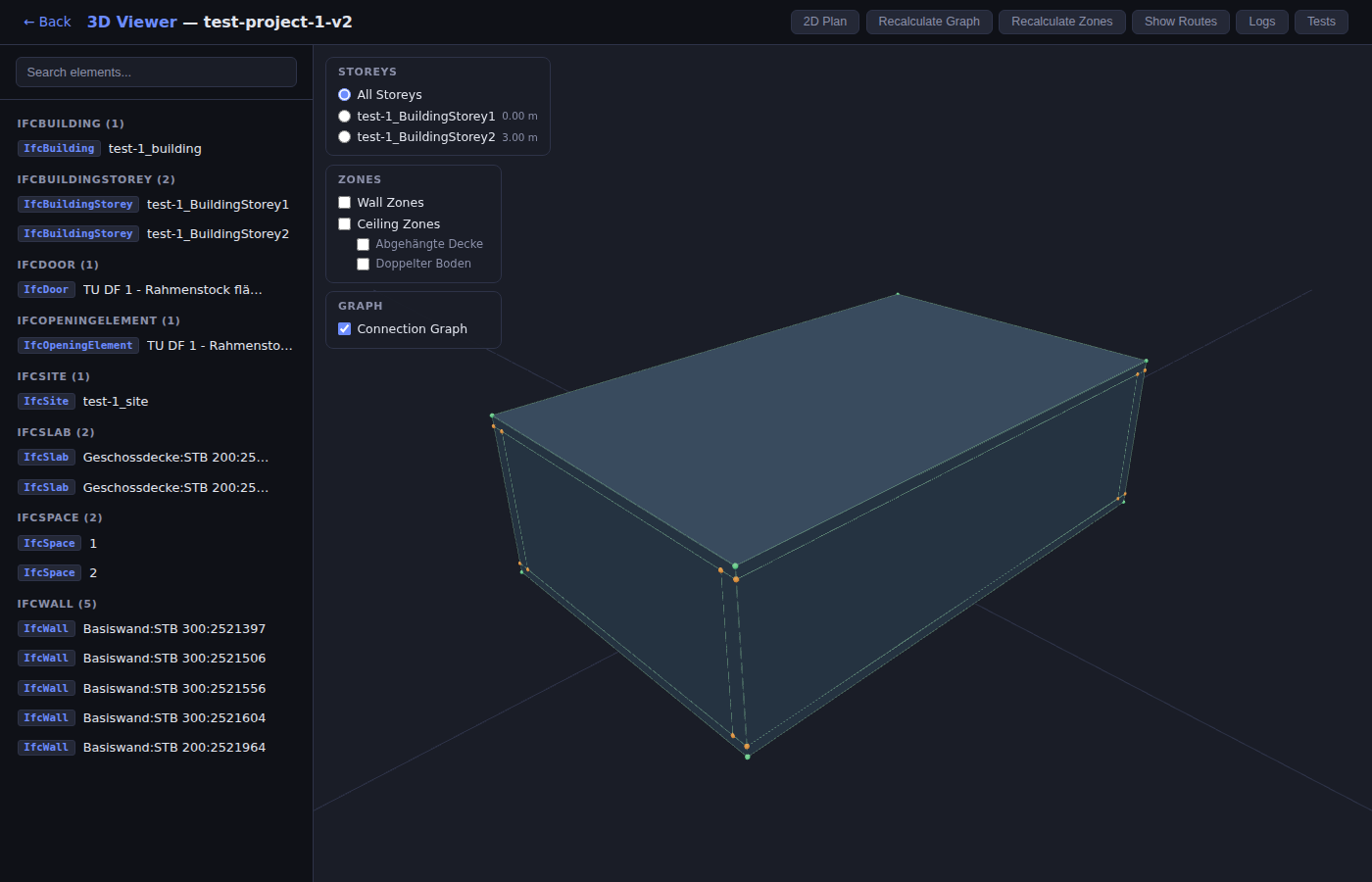
- Toggle: "Show Graph" / "Hide Graph" button in viewer header
- Green spheres (radius 0.04m): internal nodes
- Orange spheres: nodes that participate in external edges (junction points)
- Green lines: internal edges (element wireframes)
- Orange lines: external edges (cross-element connections)
- All coordinates transformed via
ifcToThree()before rendering
Example Output (test-1.ifc)
- 114 nodes, 174 edges (136 internal + 44 external)
- 5 walls, 1 door, 2 slabs, 2 spaces = 10 elements processed
- External connections include: wall↔wall corners, wall↔door frame, wall↔slab edges, wall↔space corners