DIN 18015-3 Installation Zone Visualization
Purpose
Computes and visualizes cable installation zones on wall and ceiling surfaces according to German electrical norms (DIN 18015-3). Shows where cables can go (green), where they normally run (blue), and where they're forbidden (red).
Normative Source
Based on Kabelverlegung in Wohnungen und Büros.md which contains machine-readable
parameters derived from DIN 18015-3 and DIN VDE 0100-520.
Files
| File | Role |
|---|---|
tools/_wall_zones.py |
Wall zone computation + ceiling zone integration |
tools/_ceiling_zones.py |
Ceiling zone computation (per IfcSpace) |
app.py route /wall_zones/<filename> |
API endpoint with caching |
Kabelverlegung in Wohnungen und Büros.md |
Normative reference (German) |
Zone Measurements
Horizontal Zones (along wall length)
| Zone | Code | From | Width | Color | Purpose |
|---|---|---|---|---|---|
| Upper | ZW-o | 15cm from ceiling | 30cm | Green | Main cable distribution, ceiling lighting |
| Lower | ZW-u | 15cm from floor | 30cm | Green | Outlet ring circuits |
| Middle | ZW-m | 100cm from floor | 30cm | Green | Kitchen/office workspaces (not yet implemented) |
| Upper preferred | — | 30cm from ceiling | 2cm | Blue | Preferred cable centerline |
| Lower preferred | — | 30cm from floor | 2cm | Blue | Preferred cable centerline |
Vertical Zones (floor to ceiling)
| Zone | Code | From Edge | Width | Color | Purpose |
|---|---|---|---|---|---|
| Door | ZS-t | 10cm from door frame | 20cm | Green | Light switch wiring |
| Corner | ZS-e | 10cm from wall corner | 20cm | Green | Wall-to-wall transitions |
| Door preferred | — | 15cm from door frame | 2cm | Blue | Preferred cable centerline |
| Corner preferred | — | 15cm from corner | 2cm | Blue | Preferred cable centerline |
Absolute Forbidden Areas (Dark Red)
These are structural exclusion zones — never place cables here.
| Area | Measurement | Reason |
|---|---|---|
| Ceiling strip | 0–15cm from ceiling | Structural zone (ring anchors, lintels) |
| Floor strip | 0–15cm from floor | Structural zone |
| Door exclusion | 0–10cm from door edge | Frame/structural clearance |
| Corner exclusion | 0–10cm from wall corner | Masonry bonds, structural columns |
| Door opening | Full door rectangle | No cables through openings |
Vertical Transit Zone (Yellow)
The "dead zone" between horizontal zones. Cables cannot run horizontally here, but a vertical Stichleitung (perpendicular feed line) is allowed to connect a device to the nearest horizontal zone above or below.
| Area | Measurement | Rule |
|---|---|---|
| Dead zone | Between ZW-u top (45cm from floor) and ZW-o bottom (45cm from ceiling), outside vertical zones | Vertical transit only — go straight up/down to reach ZW-o or ZW-u |
Cable Depth Constraints
Computed per-wall by _get_max_depth_mm(thickness_m, is_load_bearing) using wall
thickness from IFC geometry and LoadBearing from Pset_WallCommon.
By Wall Thickness (automated):
| Wall Thickness | Max Depth | Applied When |
|---|---|---|
| < 115mm | 10mm | Very thin partition |
| 115–149mm | 10mm | Light partition |
| 150–174mm | 20mm | Standard partition |
| 175mm+ | 30mm | Standard/thick wall |
By Material (reference, not yet auto-detected):
| Wall Material | Max Depth | Max Width |
|---|---|---|
| Load-bearing | 30mm | 15mm |
| Non-load-bearing | 30mm | 30mm |
| Concrete | 20mm | 15mm |
| Aerated concrete | 40mm | 30mm |
| Special: ≤1m from floor, wall ≥240mm | 80mm | 120mm |
Each green zone carries its wall-specific depth_mm value in the JSON output.
Calculation Steps
Step 1: Wall Analysis
For each wall:
1. Compute thin_axis (thickness direction) via np.argmin(wall_size[:2])
2. Two faces: face_a = bbox_min[thin_axis], face_b = bbox_max[thin_axis]
3. Wall surface is a rectangle: u_min→u_max (along long axis) × v_min→v_max (floor to ceiling)
4. Extract LoadBearing from Pset_WallCommon via _get_wall_properties()
5. Compute depth_mm from wall thickness via _get_max_depth_mm() — stored on every green zone
Step 2: Junction Detection (_detect_junctions)
Finds ALL points where other walls meet this wall:
- End junctions: where this wall's end meets a perpendicular wall → type
"end" - T-junctions: where a perpendicular wall meets this wall mid-span → type
"t_junction", generates two junction points (at both edges of the intersecting wall's thickness) - Parallel junctions: end-to-end connections → type
"end"
T-junctions are critical: they split the wall into segments, each getting its own set of ZS-e corner zones and independent horizontal zones.
Step 3: Exterior Face Detection (_is_face_interior)
For each wall face, checks if a room (IfcSpace) is adjacent:
- Gets space bounding boxes
- For min-face: checks if any space has
bbox_max[thin_axis] ≈ face_coord - For max-face: checks if any space has
bbox_min[thin_axis] ≈ face_coord - Exterior faces get no zones (no cables on building exterior)
- Interior faces get full zone computation
Step 4: Zone Generation (_compute_face_zones)
For each interior face:
- Collect split points from T-junctions
- Generate horizontal zones for each segment between split points:
- ZW-o (upper green), ZW-u (lower green)
- Segments interrupted at T-junctions
- Generate door zones (ZS-t):
- Green vertical strip on each side of door frame (10-30cm from edge)
- Red forbidden strip (0-10cm from edge)
- Red door opening rectangle
- Generate corner zones (ZS-e):
- At wall ends: green strip going inward
- At T-junctions: green strips on BOTH sides + red forbidden strip at junction
- Generate forbidden zones (dark red):
- Ceiling/floor red strips (0-15cm)
- Door/corner exclusion (0-10cm from edges)
- Door opening rectangles
- Generate dead zones (yellow):
- Segments between vertical zones in the mid-wall area (between ZW-u top and ZW-o bottom)
- Vertical Stichleitung allowed here, horizontal cables forbidden
- Generate blue preferred paths:
- Thin 2cm strips at zone centers (30cm from ceiling/floor, 15cm from edges)
Step 5: Mode Variants
Query parameter ?mode=normal|false_ceiling|false_floor:
| Mode | ZW-o | ZW-u | Ceiling forbidden | Floor forbidden |
|---|---|---|---|---|
normal |
Standard (15-45cm from ceiling) | Standard (15-45cm from floor) | Yes (0-15cm) | Yes (0-15cm) |
false_ceiling |
Expanded (0-45cm from ceiling) | Standard | No | Yes |
false_floor |
Standard | Removed | Yes | No |
Step 6: Ceiling Zone Computation (tools/_ceiling_zones.py)
Ceiling zones are computed per IfcSpace (per room), not per slab. A single IfcSlab
spans the entire storey; walls divide the space below into rooms.
- Ceiling Z:
space.bbox_max[2](top of room = ceiling surface from below) - Slab thickness: found by matching slab whose
bbox_min[2]is nearspace.bbox_max[2](metadata only) - Room footprint:
space.bbox_min/maxin X/Y defines the ceiling rectangle
Solid Ceiling Zones (normal mode)
| Zone | Code | Position | Width | Color |
|---|---|---|---|---|
| Room perimeter | ZD-r | 20cm from wall | 30cm | Green |
| Door passage | ZD-t | 15cm from passage wall | 30cm | Green |
| Edge forbidden | — | 0–20cm from wall | 20cm | Red |
| Interior dead zone | ZD-dead | Inside the ZD-r ring (>50cm from walls) | varies | Yellow |
| Preferred paths | ZD-r center | Center of each ZD-r band (35cm from wall) | 2cm | Blue |
Door-space association: doors are matched to spaces by geometric proximity to space faces.
False Ceiling Zones (false_ceiling mode)
Single green rectangle per room, 10cm below ceiling surface, covering the full room footprint.
Includes metadata flags:
- strain_relief_required: true
- max_tension_install_n_mm2: 50 (during cable installation)
- max_tension_permanent_n_mm2: 15 (permanent load, requires cable trays)
Step 7: Caching
Saved as uploads/<stem>.wall_zones_<mode>.json. Loaded from cache on subsequent requests.
JSON Output Structure
{
  "walls": [{
    "wall_id": 291,
    "wall_name": "Basiswand:STB 200:2521964",
    "thickness_m": 0.2,
    "is_load_bearing": false,
    "max_depth_mm": 30,
    "faces": [{
      "face_coord": 5.1,
      "thin_axis": 1,
      "long_axis": 0,
      "u_range": [0.3, 6.3],
      "v_range": [0.0, 2.8],
      "is_interior": true,
      "zones": [
        {"type": "ZW_o", "category": "green", "depth_mm": 30,
         "corners": [[0.3, 5.1, 2.35], [6.3, 5.1, 2.35], [6.3, 5.1, 2.65], [0.3, 5.1, 2.65]]},
        {"type": "forbidden_ceiling", "category": "red",
         "corners": [[0.3, 5.1, 2.65], [6.3, 5.1, 2.65], [6.3, 5.1, 2.8], [0.3, 5.1, 2.8]]},
        {"type": "ZW_o_center", "category": "blue",
         "corners": [[0.3, 5.1, 2.49], [6.3, 5.1, 2.49], [6.3, 5.1, 2.51], [0.3, 5.1, 2.51]]}
      ]
    }]
  }],
  "ceilings": [{
    "space_id": 46,
    "space_name": "Raum 1",
    "ceiling_z": 2.4384,
    "slab_thickness_m": 0.2,
    "zones": [
      {"type": "ZD_r", "category": "green",
       "corners": [[0.5, 5.5, 2.44], [6.1, 5.5, 2.44], [6.1, 5.8, 2.44], [0.5, 5.8, 2.44]]},
      {"type": "ZD_false_ceiling", "category": "green",
       "strain_relief_required": true,
       "max_tension_install_n_mm2": 50,
       "max_tension_permanent_n_mm2": 15,
       "corners": [[0.3, 5.3, 2.34], [6.3, 5.3, 2.34], [6.3, 10.1, 2.34], [0.3, 10.1, 2.34]]}
    ]
  }],
  "mode": "normal",
  "stats": {"wall_count": 5, "zone_count": 207, "ceiling_count": 2, "ceiling_zone_count": 28}
}
Viewer Visualization
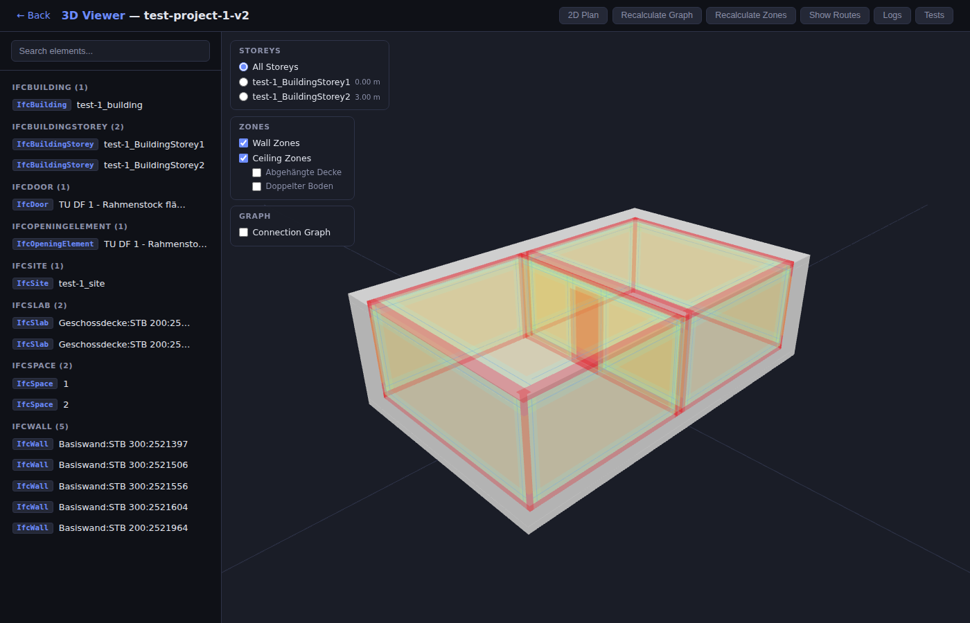
- Checkboxes: "Wall Zones", "Ceiling Zones" (independent toggles)
- Mode options: "Abgehängte Decke" (false ceiling), "Doppelter Boden" (raised floor)
- Storey-aware: zones filtered by active storey selection
Color Scheme
| Color | Category | Opacity | Meaning |
|---|---|---|---|
Dark Red (#cc2222) |
red |
0.30 | Absolute forbidden — NEVER put cables here (structural exclusion, door frames, corners, openings) |
Yellow (#ddaa22) |
yellow |
0.20 | Vertical transit only — can go straight up/down as Stichleitung, but NO horizontal cables |
Green (#44ff44) |
green |
0.20 | Installation corridors — cables allowed here, depth limited by wall type |
Blue (#4488ff) |
blue |
0.40 | Preferred cable paths — center of installation corridors |
Rendering Details
- Batched rendering: all zone quads of the same color category are merged into a
single
THREE.BufferGeometry(~8 total meshes instead of one per zone). This reduces 50,000+ individual objects to ~8 for large models. THREE.MeshBasicMaterial(flat, unlit) withdepthTest: false,depthWrite: false- Zone groups use
renderOrder: 1so they always render on top of wall geometry - Zone data cached in JS (
zoneDataCache); storey filter rebuilds merged geometry from cache